 Dave's Speaker Pages
Dave's Speaker Pages
Dave's Speaker Pages

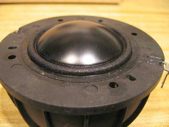
Dayton Loudspeakers has introduced a new midrange driver in their Dayton Reference Series line, the RS52AN-8. I purchased a pair, both to conduct some tests and to try out in a 3-way. It's a 2" metal dome with a mesh cover for protection and has no phase shield, not normally found on a midrange driver. More on that topic later.
As a limited low-frequency midrange, this driver is very good right out of the box. I was impressed with the assembly quality on initial visual inspection. Subsequent measurements on my large baffle reinforced this impression. The pair measured fairly closely, both in SPL and impedance, to include Fs center and peak. Fs is one parameter that is too often found to vary significantly from spec in lesser quality drivers and at times in "good" drivers. This is important due to the possible interaction with the highpass of a crossover.
A Few Measurements (Did I say a few?)
Initial measurements on my 2mx2m baffle show the response to be smooth and extended, with a rather severe breakup at the top end. This is to be expected, since the dome is coated metal. As can be seen below, the breakup is significant enough to create a glitch in the impedance curve. There is what appears to be a small, low-Q peak centered at 2KHz.

My interest in this driver is as much to test it for modifications as much as to use it in a system. I've been curious about hard-domed midrange units that don't have phase shields, even though most hard-domed tweeters do, so my testing was focused on this aspect. After making initial measurements before modifications to use as a reference, I began testing various applications of felt as a phase shield. My thoughts were that felt would make a better shield since it has absorptive properties and might reduce the amount of reflected sound that is the hallmark of most phase shields that are formed from hard materials.
Real wool usually makes the best absorptive material for such as task. However, I've found that the readily available small brown discs found in craft shops and hardware stores works fairly well. They're certainly easier to procure. The softest variety is preferable. Most of my testing used these.
NOTE: I've chosen to have pictures that may show some additional pieces of felt applied to reduce the total number of pictures required. In the preceding paragraph I refer to the case where the disc alone was used. Also, most of my comments relate to the on-axis, but I did follow up with off-axis measurements as well and found that there is a tradeoff between on-axis and off-axis. More on that later as well.
The first test was a round piece of the softest variety, 3/4" in diameter. There was a distinct improvement, so I tested with a smaller, 5/8" disc. This was similar. I later tested these on the inside, as seen in the picture below. I'm not sure what I would suggest as the optimal solution for use of a disc in the center only, 5/8" or 3/4". All subsequent tests used the center piece as a given in any case.
RS52 response comparisons of single disc inside
As I proceeded with tests of multiple discs of varying sizes placed in various patterns I noticed that the breakup beyond the peak was seldom influenced. I deduced that this is because this region is an artifact primarly of the surround and the dome response near the surround. I placed a ring of discs around the periphery of the protective mesh in an attempt to alter this, with some success. I ultimately rejected this due to the negative influence in the off-axis response.

Soft Felt (craft) Disc in Center - 3/4" - with ring of discs
Another issue I investigated is the small volume under the mesh cover where it is attached to the motor frame. Any part of the driver structure that has an undamped or unreleaved volume of air can create resonances. I initially cut a small strip of 1/4" felt that was an improvement. I bought some felt "wicking" in a later purchase that appeared to be perfect for the task. It's an F5, 100% wool content soft felt that can be easily cut and positioned. It doesn't even have to be glued into place. I cut it about 1/4" longer than the diameter needed, then set it into place. The extra length applies just enough force to keep it in place.

|

|
Continuing tests of various pattern, a more successful one was a pattern of smaller, 1/2" discs. Placed in a square pattern (4 corner pieces) around the center piece actually improved it again. Next I filled in the gaps in between that resulted in an eight-piece square around the center piece. This is possibly the optimal pattern. I eventually duplicated this on the inside. In the end placing them in a plain circular pattern was pretty much equivalent. The white felt in the rim of the photo had not yet been added for these measurements.

Soft (craft) Felt Disc in Center - 3/4" - with square disc pattern and rim felt
Back to the disc alone, the most extended response I'd found to this point on-axis, though not the flattest, is shown in isolation below. It used a single 5/8" disc, in this case, one that I cut from some SAE F-5 I had on-hand. Looks pretty good considering the on-axis only, doesn't it? It can be argued that this is all that is necessary for a good response, since some response shaping can linearize the slight droop in optimizing the bandpass crossover.
RS52 most extended on-axis response
Now let's look at the isolated SPL response for the pattern that gave the flattest response in the middle of the drivers usable passband, in the 1.5-8KHz range. It may be possible to design a baffle with dimensions and driver placement that will position the peak above baffle step in the area just below the driver's upper shelf. This, coupled with a good crossover, might provide an extremely flat response from 800-8000Hz. This, of course, will require some baffle diffraction control as well, such as roundovers or felt treatment. But it should be doable. I'm going to make the attempt.

RS52 flattest on-axis response
The off-axis must be considered if a proper analysis is to be made. In this case it doesn't look quite as good as you were expecting, I'll bet. Something about that breakup hardly dropping in level relative to the rest of it that just sticks out. Note that this graph alone has 10db/division in order to view more of the breakup region.

RS52 flattest response family
What about the off-axis of the various felt configurations? The results surprised me and caused me a bit of consternation. I tweaked the on-axis getting good results that I planned to keep. Then I saw these off-axis results. Only the 60° responses are shown here as they are representative of most of the off-axis. At times the results worsened the more off-axis the measurement point. The problem is that the peak either stayed the same or even increased in magnitude. Note in the graph below how the best response is that of the native, unmodified driver.

RS52 off-axis comparisons
There is a lot of space between dome and protective grill, so continuing to experiment, I doubled up on the disc inside (the craft variety) going back to the ¾" version that is ¼" when doubled. This also has the F26 on the outside, but I did this due as much to the muted gray color. The off-axis may still not be as good as it is for other sizes/layouts. The overlayed blue curve shows the effect of adding the small felt rope around the internal rim. On this axis it would appear to be less than effective when used with the doubled-up internal felt disc. One problem is that the Q of the peak is increased.


Nothing had been too surprising so far, except for that 60° off-axis result. But with more experimenting I realized two things that really were surprising to me. Look at the yellow curve in the next graph as compared to the other, modifed responses. One observation is obvious, the other is deduced from studying the results of the various felt pattern changes.

Untreated vs. various felt patterns
The first thing I noticed was confirmation of what I had seen in the first CSD (waterfall) graph, shown again for convenience. The low-Q peak at 2KHz has been referred to as a resonance. If you look closely at that CSD, you'll note that there's almost no indication whatsoever of a resonance ridge, although there does seem to be just the smallest influence on the impedance profile. I found this to be very intriguing, as I'd often wondered if this situation could occur. The question now is, how can this happen?
RS52 New On-Axis
The answer is to be found in studying the changes in the SPL response with the various felt applications. The key is in realizing that each time more felt was applied, the response between the 2K "peak" and upper response actually increased in level. In fact, it could be said that adding the felt increased the drivers sensitivity by 2db in middle of he passband in the more extreme case. This is evidenced by the increased output between 1K and 6K. It increased slightly as shown in the red curve and even more in the yellow curve. How has this happened you may be asking? The answer lies in examining just what happens when the felt (or phase shield) is added. This, I believe, is how the term phase shield originates.
A Phase-Shield Primer
Hard-domed tweeters, in most cases, include what is called a "phase shield". This is usually in the form of a disc-shaped piece of material supported, in one way or another, directly in front of the dome and centered on it. It's not been used in hard-domed midrange drivers at all, to my knowledge.
There is at times some misunderstanding of just what this shield does. It doesn't alter phase per se, as it cannot alter the phase of the signal as it emerges from the dome. Its purpose is to block the output from the tip of the tweeter, the reason being that at the upper range of tweeters, somewhere around 10KHz and up, the signal emanating from the tip will actually arrive at the listener prior to that sound emanating from the rim, where the former attaches to the diaphragm. At high frequencies the time difference is significant enough that there is a phase delta that causes interference to occur.
The reason that this occurs is because a hard-domed diaphragm is pistonic to a much higher frequency than softer diaphragms. Essentially, the speed of sound is much faster in the hard material than it is in air, it therefore reachs the tip and emanates form it before the sound passing through the air originating from the diaphragm rim area can reach the equivalent distance out from the driver.
To visualize this, look at the picture below and note the height of the dome. In the RS52, this is about 9 or 10 mm. Assuming 9mm, this translates into a frequency of 344,000mm / 9mm = 17,200 Hz for a full wavelength. The maximum interference at this frequency will be when the phase is 180° out-of-phase, or half a wavelength. This yields 19,111Hz. Note the severe null around this frequency in the original driver measurement above. This is not precise, since the entire dome radiates and each concentric ring examined on the dome is at a different distance than the next concentric ring, but this demonstrates the issue. It's entirely possible that the extreme null is more a function of the output of the hard dome near the rim and the surround that will itself radiate sound energy as well. I don't have any facilities to make firm conclusions of the details.
The phase shield is not intended to impact this region. That's because the peak is due to the movement of the dome at the rim where it is attached to the former. Usually the driver is designed to place this point above 20KHz, hoping that it is not audible. The phase plug, though will reduce a portion of the output that is partially out-of-phase and that typically causes a droop in the reponse below the peak. There appears to only a very small droop in the RS52 related to this.
Hard materials also have very little internal self-damping. This means that the signal has little attenuation as it travels through the diaphragm. In comparison, treated soft-domes have a significant amount of internal damping. In some cases, soft domes are highly optimized to significantly attenuate the signal very smoothly in order to provide a more extended response. A good example of this is the Hiquphon OW1.
In it's pistonic range, the dome radiates sound at nearly the same time from all points on the diaphragm, since it's a hard dome. The result is that the speed of sound in it is much higher than it is in air. For simplicity, consider only the signal from the dome tip and the dome rim. The sound emitted from the closer points (the center in the example) arrives at the measurement point before the sound that is emitted from the rim area. That is, the two signals are not fully in phase. For the lower frequencies, this causes little difference in the summed response (a vector sum). Nothing extraordinary so far.
The felt pieces placed on the cover grill block the signal from all points on the dome that are out of view on the axis examined. In other words, the felt blocks some of the signals that, due to differing distance, are partially out-of-phase. The impact is small at lower frequencies, since the total acoustic output from the dome does not change and at low frequencies it just moves around the felt and has little phase variation, thus there is no corresponding decrease in sensitivity at the lower frequencies because the wavelengths are too long. The effect is primarily at the upper end of the frequency range where the phase relationship is changing and the distance from dome to shield is a significant part of a wavelength. Thus the term phase-shield. It's a bit of a misnomer as it's really just a "sound wave blocker" so-to-speak, but that's the accepted terminology.
The Surprise
In essence, the drop in the region from 1K-10KHz is due, I believe, to phase issues in the dome output, not resonances of any kind. The vector sum of the output results in some droop from nominally flat response that would result if the dome were actually a flat diaphragm. Thus there is an apparent resonance at 2KHz that is actually a vector sum droop above that point. This is seen and modifiable with a phase shield in tweeters in like manner.
But what about the area below 2KHz you may ask? That is still likely to be from some internal resonance behind the dome. I would guess the distance from the front area of the dome to the rear of the motor to be around 2¼". For there to be a loss in output, the reflected signal would need to be out-of-phase, thus the distance would have to be somewhere around a quarter of a wavelength, since as a reflected signal it will have to make a round-trip. Taking my rough guess yields (13,550/2.25)/4 = 1505Hz, right in the region where the dip occurs. Below that theres a slowly decreasing interference as the wavelength increases. Eventually any reflected signal is not an issue and the knee and rolloff area are unaffected. Again, this is easily verified with tweeters that I've modified with pole-piece damping.
I think that this driver is constructed differently internally, but it appears that there are still some partially undamped reflections from the back of the motor, though not severe.
In closing I thought I'd put up the graph of the pair that I have to show the unit-to-unit consistency.

Overall I'm impressed with this driver. It's hard to beat for the cost as a limited low-end extension midrange driver.