
|
1 Oct 2022- Version 1.004 Released
No functional change, only one small aesthetic addition.

11 Jan 2020- Version 1.003 Released
This is another minor update. The export function that allows setting a reference SPL didn't change the output. It stayed at the default 90. Now the output nominal SPL will be according to the setting. This was ready two years ago, but I somehow missed adding the update to this site.
4 Jan 2018 - Version 1.002 Released
This is a minor update. The graph scales at the right for the vertical axis now includes one group delay. The scale range changes with the values of the two legs so that the upper limit is set to the maximum value of whichever section is higher, lowpass or highpass.
13 Mar 2016 - Version 1.000 Released
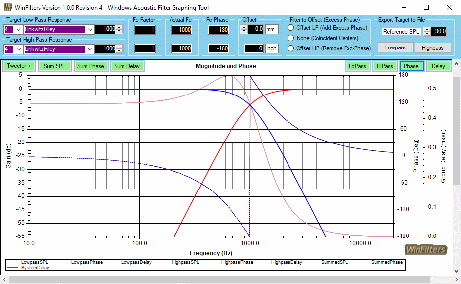
WinFilters is a small stand-alone Windows application. It started out as a simple graph for me to use in verifying that the Bessel filter target used in WinPCD was accurate. However, in order to do that, I wanted to be able to create and sum lowpass and highpass. But to do that, I had to generate phase. The targets in WinPCD are magnitude only, that's all that it requires.
In order to do that, I had to work out the s-plane equations for phase for each target filter and order. Before that, it was necessary to understand Bessel filters. In researching I found that there is a standard Bessel filter transfer function, but there are varying implementations, either for specific lowpass time delay or specific crossover characteristics, although the latter was never originally an intended usage. In essence, there is a continuum of crossovers based on separation of lowpass and highpass Fc. The best single reference that I found to describe this is at the Rane web site. It was an interesting exercise. In the course of creating the graphs for my purpose, I decided that it could just as easily be a separate program that others might find helpful for understanding classical crossovers and what happens with mixed-mode filters and offsets.
The essence of the program is that it generates a pair of filter transfer functions, lowpass and highpass, magnitude, phase and group delay (except for highpass). These are combined to show the magnitude, phase and group delay of the system response. The filters are all normalized. They can be considered to be electrical or acoustic, the transfer function for each is the same, they are minimum-phase, but with one difference. The acoustic response would be typically from two separate acoustic sources that are not coincident. That means that there is an offset that introduces excess-phase between them.
The program provides the ability to introduce excess-phase to one or the other of the filters. It's the equivalent of either moving the woofer in the negatively (adding excess-phase) direction or moving the tweeter postively (removing excess-phase). but since they are minimum-phase to start, removing excess-phase from the tweeter is the as removing too much phase from a driver measurement. It shows the odd change in the phase when this occurs. As you'll note, the summed response remains unchanged since the result in relative offset remains the same, lowpass (woofer) "farther away" or highpass (tweeter) "closer", though in this case, closer isn't an accurate way to describe it since it's removing phase from an already minimum-phase response.
The filter types available are:
One surprise is the system response of the"flattest response" Bessel. It consists of Bessel lowpass and highpass with a specific Fc separation, shown below. But consider that this is the on-axis response only. A project could be created inWinPCD using the flat files for drivers (SPL @90db and impedance @8ohms) with these targets. A crossover could then be made to match very closely that would then allow examination of the off-axis response. Eventually I will do that and will probably update this page with that info.
This effort was prompted by a question about the (lone) Bessel filter originally implemented in WinPCD. The user wondered why the "Fc changed so much" in the targets. Going from an L-R or Butterworth drastically shifted the curve and had the appearance of being wrong. However, note below that although this filter appears to have an Fc at 1K, in reality the lowpass Fc is at 400Hz and the highpass is at 2500Hz. The transfer function as defined for the commonly used Bessel is down about 0.63db at Fc. Keep in mind that this Bessel filter (lowpass) is defined to provide a specific delay and is not one used in a crossover network and that the lowpass delay has no peaking.
There are no plans to do anything further with it with the addition of the Group Delay scale addition.

